


디지털논리회로에서 여러 신호 중 하나를 선택할 때 Multiplexer(Mux)를 사용합니다. 오늘은 4-to-1 Mux를 structural design과 if문, case문으로 구현해 보겠습니다.
- IDE: Intel Quartus 18.1
- Device: Cyclone V 5CSXFC6D6F31C6(밑에서 6번째)
- Simulation: ModelSim-Altera, Verilog HDL
- Project Name & the name of Top-level: mx4
목차
1. Structural Design
1.1. mx2.v
1.2. mx4.v
1.3. tb_mx4.v
1.4. simulation\modelsim\tv_tv_mx4.v
1.5. RTL View
1.6. RTL Simulation
1.7. Flow Summary
2. if문을 사용하는 방법
2.1. mx4.v
2.2. tb_mx4.v & simulation\modelsim\tv_tv_mx4.v
2.3. RTL View
2.4. RTL Simulation
2.5. Flow Summary
3. case문을 사용하는 방법
3.1. mx4.v
3.2. tb_mx4.v & simulation\modelsim\tv_tv_mx4.v
3.3. RTL View
3.4. RTL Simulation
3.5. Flow Summary
1. Structural Design
1.1. mx2.v
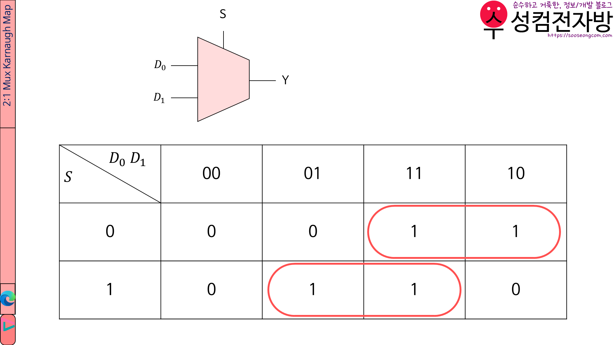
mx2.v에서는 2-to-1 Mux를 만듭니다.
Karnaugh Map을 그려 보면 2-to-1 Mux의 boolean eqation은 \(Y=D_0\bar{S}+D_1S\)임을 알 수 있습니다.
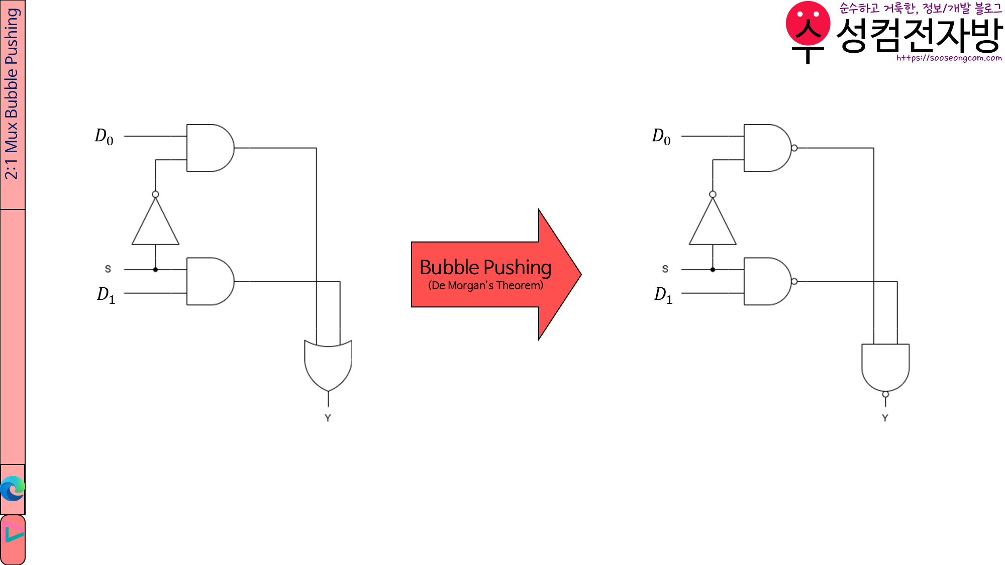
그러나 AND, OR Gate보다 NAND Gate가 더 저렴하므로 forward로 bubble pushing을 하겠습니다.
module mx2(y, s, d0, d1);
	input s;	//select signal
	input d0, d1;	//data
	output y;
	wire w0, w1, sb;

	not(sb, s);
	nand(w0, d0, sb);
	nand(w1, d1, s);
	nand(y, w0, w1);
endmodule
1.2. mx4.v
module mx4(y, s, d0, d1, d2, d3);
	input [1:0] s;	//select signal
	input d0, d1, d2, d3;	//data
	output y;

	//instance MAB: Bth mux whose select signal is s[A]
	mx2 M00(w00, s[0], d0, d1);
	mx2 M01(w01, s[0], d2, d3);
	mx2 M10(y, s[1], w00, w01);
endmodule
[Line 2]
input [1:0] s;
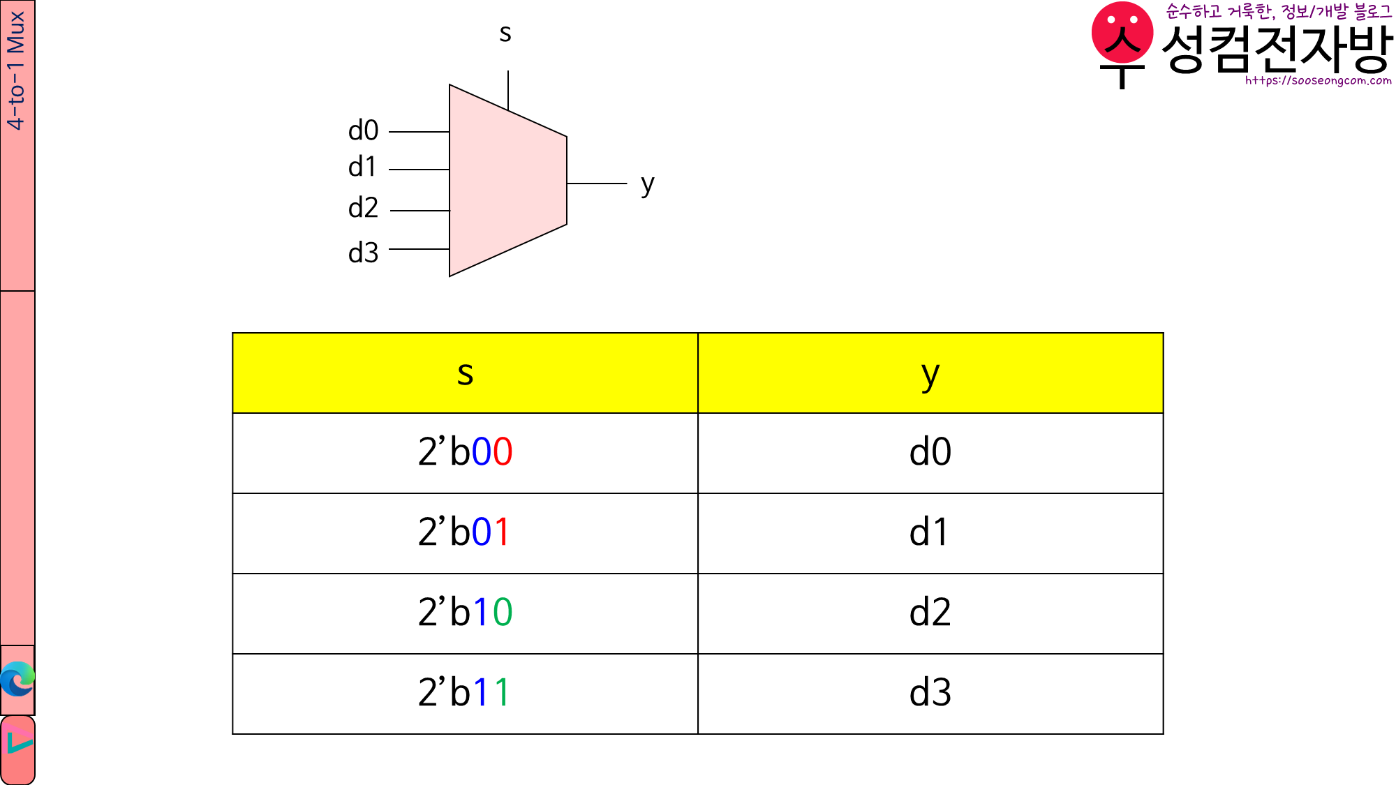
N-to-1 Mux의 s의 비트 길이는 \(\log_2 N\)입니다. 우리는 지금 4-to-1 Mux를 만들려고 하므로 s의 길이는 \(\log_2 4=2\)입니다.
[Line 6~9 instance 이름 규칙]
MAB는 select signal이 s[A]인 B번째 Mux입니다.
[Line 7]
mx2 M00(w00, s[0], d0, d1);
s[0]==0이면 d0을,
s[0]==1이면 d1을 출력합니다.
[Line 8]
mx2 M01(w01, s[0], d2, d3);
s[0]==0이면 d2을,
s[0]==1이면 d3을 출력합니다.
[Line 9]
mx2 M10(y, s[1], w00, w01);
s[1]==0이면 w00을,
s[1]==1이면 w01을 출력합니다.
1.3. tb_mx4.v
`timescale 1ns/100ps

module tb_mx4();
	reg clk, reset;
	reg [1:0] s;
	reg d0, d1, d2, d3, y_expected;
	wire y;
	reg [31:0] vectornum, errors;	//bookkeeping variables
	reg [31:0] testvectors[10000:0];	//array of testvectors

	//instantiate device under test
	mx4 dut(y, s, d0, d1, d2, d3);

	//generate clock
	always
		begin
			clk=1; #5; clk=0; #5;
		end

	//at start of test, load vectors and pulse reset
	initial
		begin
			$readmemb("./tv_mx4.tv", testvectors);	//Put testvector file at simulation\modelsim
			vectornum=0; errors=0;
			reset=1; #27; reset=0;
		end

	//apply test vectors on rising edge of clk
	always @(posedge clk)
		begin
			#1; {s, d0, d1, d2, d3, y_expected}=testvectors[vectornum];
		end

	//check results on falling edge of clk
	always @(negedge clk)
		if(~reset) begin //skip during reset==1
			if(y!==y_expected) begin
				$display("Error: inputs=%b", {s, d0, d1, d2, d3});
				$display("	outputs=%b (%b expected)", y, y_expected);
				errors=errors+1;
			end

	//increment array index and read next testvector
			vectornum=vectornum+1;
			if(testvectors[vectornum]===32'bx) begin
				$display("%d tests completed with %d errors.", vectornum, errors);
				$finish;
			end
		end
endmodule
1.4. simulation\modelsim\tv_tv_mx4.v
00_0000_0
01_0000_0
10_0000_0
11_0000_0
00_0001_0
01_0001_0
10_0001_0
11_0001_1
00_0010_0
01_0010_0
10_0010_1
11_0010_0
00_0011_0
01_0011_0
10_0011_1
11_0011_1
00_0100_0
01_0100_1
10_0100_0
11_0100_0
00_0101_0
01_0101_1
10_0101_0
11_0101_1
00_0110_0
01_0110_1
10_0110_1
11_0110_0
00_0111_0
01_0111_1
10_0111_1
11_0111_1
00_1000_1
01_1000_0
10_1000_0
11_1000_0
00_1001_1
01_1001_0
10_1001_0
11_1001_1
00_1010_1
01_1010_0
10_1010_1
11_1010_0
00_1011_1
01_1011_0
10_1011_1
11_1011_1
00_1100_1
01_1100_1
10_1100_0
11_1100_0
00_1101_1
01_1101_1
10_1101_0
11_1101_1
00_1110_1
01_1110_1
10_1110_1
11_1110_0
00_1111_1
01_1111_1
10_1111_1
11_1111_1
각 줄이 <s>_<d0><d1><d2><d3>_<y_expected>입니다.
<s>는 2-bit입니다.
예) 10_1101_0은 s=10, d=1101, y=0입니다.
1.5. RTL View
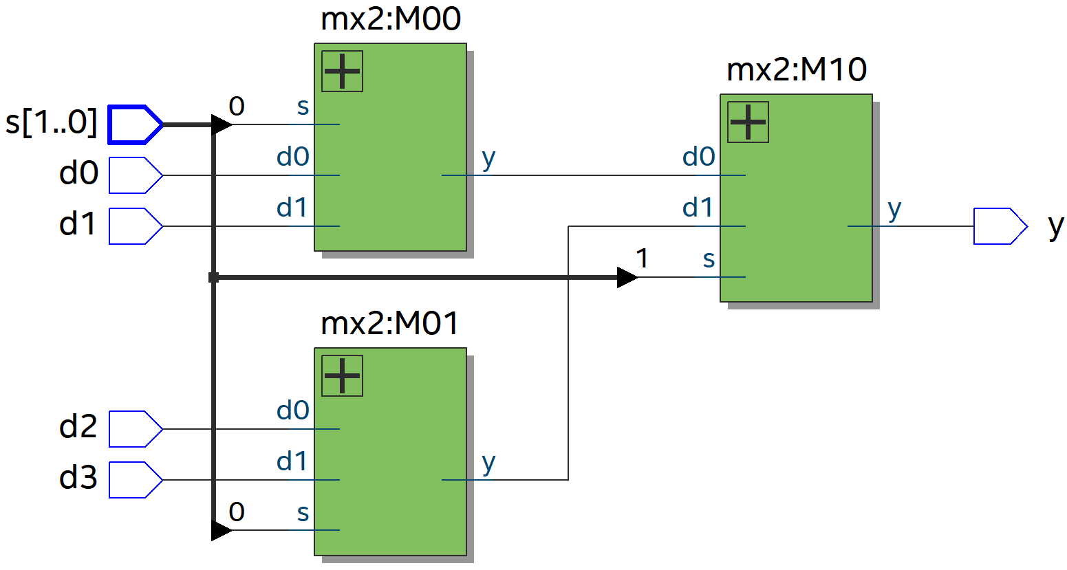
의도한 대로 mx2가 instantiation되었습니다.
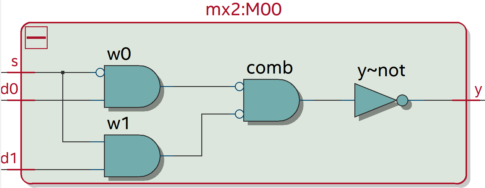
mx2를 확대해 보면 이렇게 되어 있습니다.
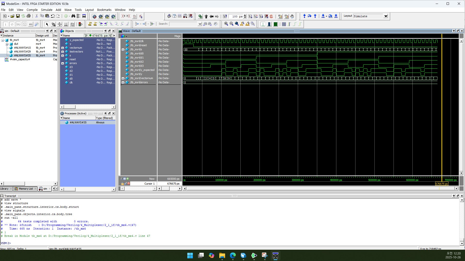
1.6. RTL Simulation

vectornum과 errors는 10진수(Decimal)로 표시하도록 설정했습니다.
1.7. Flow Summary
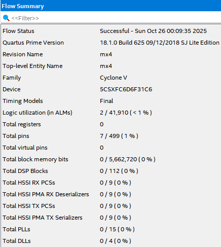
Logic utiliazation은 2, Total registers는 0, Total pins는 7이 나옵니다.
2. if문을 사용하는 방법
2.1. mx4.v
module mx4(y, s, d0, d1, d2, d3);
	input [1:0] s;	//select signal
	input d0, d1, d2, d3;	//data
	output reg y;

	always @ (*)
	begin
		if(s==2'b00)	y=d0;
		else if(s==2'b01)	y=d1;
		else if(s==2'b10)	y=d2;
		else if(s==2'b11)	y=d3;
		else y=1'bx;
	end
endmodule
[Line 4]
output reg y;
Combinational circuit이지만 always문을 사용하기 위해 y를 output reg로 선언합니다.
[Line 6]
always @ (*)
어떤 변수든 변화가 있으면 begin과 end 사이의 내용을 반복한다는 뜻입니다.
[Line 8]
if(s==2’b00) y=d0;
s==2’b00이면 y=d0;을 수행합니다.
[Line 9~11]
else if(s==2’bs값) y=데이터;
s가 01, 10, 11 중 무엇이냐에 따라 y에 d1, d2, d3을 대입합니다.
[Line 12]
else y=1’bx;
s가 00, 01, 10, 11 모두 아닐 때는 y=1’bx;를 수행합니다.
2.2. tb_mx4.v & simulation\modelsim\tv_tv_mx4.v
testbench와 testvector는 Structural Design에서 사용한 것과 동일합니다.
1.3. tb_mx4.v
1.4. simulation\modelsim\tv_tv_mx4.v
2.3. RTL View
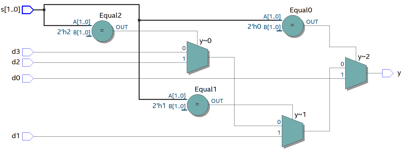
if문을 회로로 구현해 놓은 듯 보입니다.
2-to-1 Mux가 3개, Equal이 3개 있습니다.
각 Equal의 output은 2-to-1 Mux의 select signal로 들어갑니다.
2.4. RTL Simulation
Structural Design과 똑같습니다.
vectornum과 errors는 10진수(Decimal)로 표시하도록 설정했습니다.
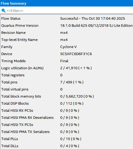
2.5. Flow Summary
Logic utiliazation은 2, Total registers는 0, Total pins는 7이 나옵니다. Structural Design과 똑같네요.
3. case문을 사용하는 방법
3.1. mx4.v
module mx4(y, s, d0, d1, d2, d3);
	input [1:0] s;	//select signal
	input d0, d1, d2, d3;	//data
	output reg y;

	always @ (*)
	begin
		case(s)
			2'b00: y=d0;
			2'b01: y=d1;
			2'b10: y=d2;
			2'b11: y=d3;
			default: y=1'bx;
		endcase
	end
endmodule
[Line 4]
output reg y;
if문을 사용할 때와 마찬가지로 case문도 always문 안에서 작동합니다. always문을 사용하기 위해 y를 output reg로 선언합니다.
[Line 6]
always @ (*)
어떤 변수든 변화가 있으면 begin과 end 사이의 내용을 반복한다는 뜻입니다.
[Line 8]
case(s)
s 값에 따라 case문이 작동하게 됩니다.
[Line 9~12]
2’bs값: y=데이터;
s가 00, 01, 10, 11 중 무엇이냐에 따라 y에 d1, d2, d3을 대입합니다.
[Line 13]
default: y=1’bx;
s가 00, 01, 10, 11 모두 아닐 때는 y=1’bx;를 수행합니다.
[Line 14]
endcase
case문을 닫습니다.
3.2. tb_mx4.v & simulation\modelsim\tv_tv_mx4.v
testbench와 testvector는 Structural Design에서 사용한 것과 동일합니다.
1.3. tb_mx4.v
1.4. simulation\modelsim\tv_tv_mx4.v
3.3. RTL View
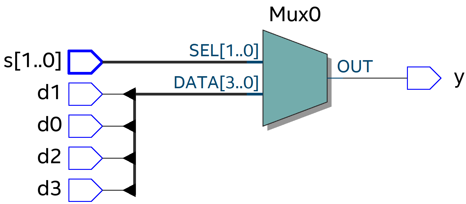
case문을 사용하니 RTL View가 Mux 기호로 구현되었습니다. RTL View는 case문이 제일 간결한 것 같네요.
3.4. RTL Simulation
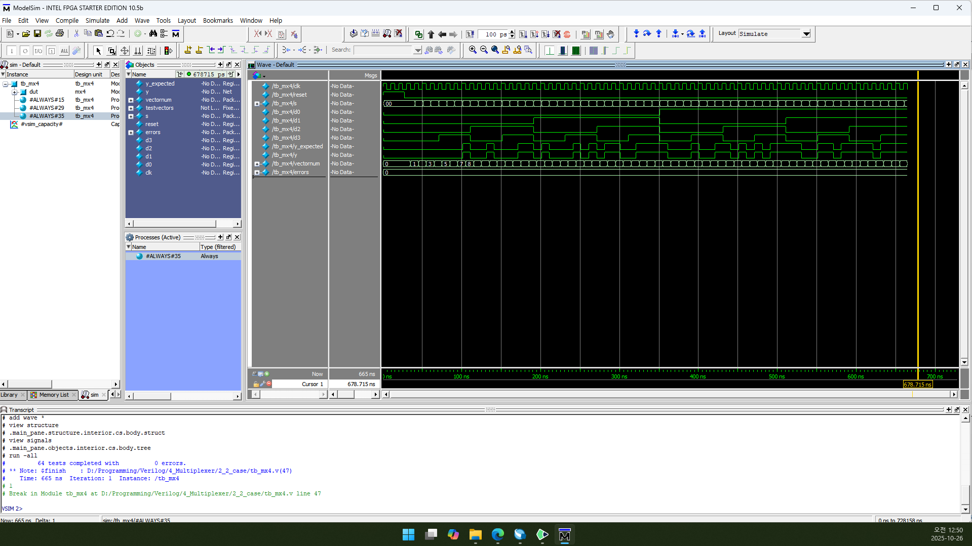
Structural Design과 똑같습니다.
vectornum과 errors는 10진수(Decimal)로 표시하도록 설정했습니다.
3.5. Flow Summary
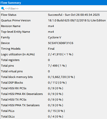
Logic utiliazation은 2, Total registers는 0, Total pins는 7이 나옵니다. 이것도 Structural Design과 똑같네요.
4. 글 마무리
Mux를 구현할 때는 case문이 가장 좋아 보이네요.
제 글을 읽어 주셔서 감사합니다. 다음에 만나요!
5. 참고 문헌
1) David Money Harris, Sarah L. Harris. 2013. Digital Design and Computer Architecture. 2nd Edition. Elsevier Korea L.L.C.